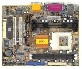
CPU
Socket LGA775 para procesadores Intel® Core™2 Extreme / Core™2 Duo / Pentium® D / Pentium® 4 / Celeron® DCompatible con procesadores Intel 05B/05A/06Listos para la tecnología Intel Hyper-Threading * Diríjase a http://www.asus.com/ para la lista de soporte de CPUs Intel* Actualice a la última versión de BIOS para soporte de CPUs Quad-core
Chipset
Intel G965 / ICH8 con tecnología Intel® Clear Video
Front Side Bus
1066 / 800 / 533 MHz
Memoria
4 x DIMM, máx. 8GB, DDR2 800* / 667 / 533 MHz, non-ECC, memoria un-buffered Arquitectura de memoria dual channel * Diríjase a http://www.asus.com/ o al manual de usuario para la QVL de memoria (Qualify Vendor List)
Slots de Expansión
1 x PCI-E x161 x PCI-E x42 x PCI 2.2
VGA
Intel® Graphics Media Accelerator X3000 (Intel® GMA X3000) integradaHigh Definition Video Processing con resolución máx. de 2048 x 1536 bpp(@ 75Hz)Máxima memoria compartida 256MBSoporta Microsoft® DX 9, OpenGL 1.5, Pixel Shader 3.0
Almacenamiento
Southbridge - 4 x Puertos SATA 3.0 Gb/s Controladora JMicron® JMB363 PATA y SATA - 1 x UltraDMA 133/100/66/33 para hasta 2 dispositivos PATA - 1 x Puerto SATA interno 3.0 Gb/s - 1 x Puerto externo SATA 3.0 Gb/s (SATA On-the-Go) - Soporta SATA RAID 0, 1 y JBOD (con 1x SATA Externo y 1x SATA Interno)
LAN
Controladora Realtek® PCI-E Gigabit LAN
Audio
ADI® AD1988 8 canales High Definition Audio CODEC - Soporta Jack-Sensing, Enumeration, Multi-streaming y Jack-Retasking - Salida S/PDIF coaxial onboard - ASUS Noise Filter
IEEE 1394
Controladora TI® 1394a soporta 2 x puertos IEEE 1394a (uno en midboard; uno en panel trasero)
USB
10 x Puertos USB 2.0 (6 puertos en mid-board, 4 puertos en panel trasero)
Características ASUS AI Lifestyle
ASUS Quiet Thermal Solution: - ASUS AI Gear - ASUS AI Nap - ASUS Advanced Q-FanASUS Crystal Sound: - Noise filterASUS EZ DIY: - ASUS Q-Connector - ASUS CrashFree BIOS 3 - ASUS EZ Flash 2
Otras características especiales ASUS
ASUS C.P.R.(CPU Parameter Recall)ASUS MyLogo 2
Puertos panel trasero I/O
1 x PS/2 Keyboard1 x PS/2 Mouse1 x Parallel port1 x External SATA 1 x VGA port1 x IEEE1394a1 x RJ45 port4 x USB 2.0/1.18-Channel Audio I/O
Conectores Internos I/O
3 x USB connectors support additional 6 USB ports1 x Floppy disk drive connector1 x IDE connector for two devices1 x COM connector5 x SATA connectors1 x CPU Fan connector1 x Chassis Fan connector1 x Power Fan connector1 x IEEE1394a connectorFront panel audio connector1 x Azalia Digital Header1 x S/PDIF Out HeaderChassis Intrusion connectorCD audio 24-pin ATX Power connector1 x 4-pin ATX 12V Power connector
BIOS
8 Mb Flash ROM, AMI BIOS, PnP, DMI2.0, WfM2.0, SM BIOS 2.3, ACPI 2.0a, ASUS EZ Flash 2, ASUS CrashFree BIOS 3
Manejabilidad
WfM 2.0, DMI 2.0, WOL by PME, WOR by PME, PXE, RPL
Accesorios
Cable UltraDMA 133/100/66 Cable FDD Cables SATACable de alimentación SATA Q-connector 3 en 1 I/O ShieldManual de usuario
CD de soporte
DriversASUS PC Probe IIASUS Update Software anti-virus (versión OEM)
Dimensiones
Dimensiones uATX, 9.6"x 9.6"(24.5cm x 24.5cm)


